

HELIUM MASS-SPECTROMETER
LEAK DETECTOR
MANUAL
(ENGLISH VERSION)
Contents
|
1 |
Safety requirements |
|
|
2 |
General information |
|
|
2.1 |
Function |
|
|
2.2 |
Technical specifications |
|
|
2.3 |
Parts list |
|
|
2.4 |
Operation principles |
|
|
2.5 |
Vacuum system of leak detector |
|
|
2.5.1 |
Mass-spectrometer analyzer |
|
|
2.5.2 |
Turbo-molecular pump |
|
|
2.5.3 |
Valves |
|
|
2.6 |
Construction of leak detector |
|
|
2.7 |
Scheme of electrical connections |
|
|
3 |
Leak detector оperation |
|
|
3.1 |
Operational restrictions |
|
|
3.2 |
Preparation for work |
|
|
3.3 |
Control panel |
|
|
3.4 |
Software |
|
|
3.5 |
Control of settings |
|
|
3.5.1 |
Settings menu |
|
|
3.5.2 |
Default settings |
|
|
3.6 |
Operating modes |
|
|
3.6.1 |
Automatic mode |
|
|
3.6.2 |
Operator’s work screen in automatic mode |
|
|
3.6.3 |
Manual mode |
|
|
3.6.4 |
Operator’s work screen in manual mode |
|
|
3.7 |
Archive screen |
|
|
3.8 |
Methods of leak detection |
|
|
4 |
Service and maintenance |
|
|
4.1 |
Cathode replacement and cleaning of mass-spectrometer analyzer |
|
|
4.2 |
Analyzer magnetic system adjustment |
|
|
4.3 |
Manual adjustment of accelerating voltage |
|
|
4.4 |
Vacuum system maintenance |
|
|
4.5 |
Cleaning of vacuum system |
|
|
5 |
Current repair |
|
|
6 |
Marking and sealing |
|
|
7 |
Storage |
|
|
8 |
Transportation |
|
|
Appendix A – Analogues of vacuum oils table |
|
|
|
Appendix B – Description of accessories |
|
|
DEAR CUSTOMER!
The leak detector TI1-50 is a modern highly automated device which allows to achieve the results of the world's best mass-spectrometer helium leak detectors.
Whereas leak detector has an easy-to-use interface, it is technically complex product. Before starting work it is necessary to read carefully this manual.
As the mаnufacturer makes permanent improvements aimed at the leak detector safety and quality level as well as its operational reliability increase, some insignificant changes which don’t influence the technical specifications and are not covered in this manual can be made in the product’s design and software.
Leak detectors TI1-50 are available in two versions, which are presented in Table 1.
Table 1
|
Item, type |
Designation |
TMP Type |
|
Leak detector ТИ1-50 |
ТФИЯ.406239.024 |
Edwards EXT75DX ISO63 |
|
Leak detector ТИ1-50-01 |
ТФИЯ.406239.024-01 |
TMHN-50/63 |
The leak detector of TI1-50 series complies with technical conditions 4215-023-07517692-2010.
This manual is intended to represent the operation principles and technical specifications of mass-spectrometer leak detectors of TI1-50 series (hereinafter referred to as ‘leak detectors’). It also contains the description of the device, it’s operation principles, technical specifications, and information required for proper installation, setting, checking, operation, maintenance, repair, storage and transportation.
Overall dimensions and appearance of leak detector basic configuration (with an inner forepump) are shown in Figure 1.

Figure 1 - Appearance and overall dimensions of leak detector basic configuration.
By agreement with the consumer, leak detector can be equipped with external forepump mounted on the transportation trolley. The appearance and overall dimensions are shown in Appendix ‘B’.
1 Safety requirements
1.1 According to the electrical safety requirements the leak detector meets the Class I requirements of protection, according to Russian national standard GOST 12.2.007.0-75.
1.2 The leak detector operation must comply with current rules of the electrical facilities use.
1.3 Leak detector is powered by an AC voltage of 220 V at 50 Hz with a protective earthing connection.
1.4 Preparation of the leak detector to work, carrying out maintenance, repair and replacement of vacuum system components must be realized when the leak detector is turned off only.
1.5 Operation of leak detector with removed covers is prohibited.
The employees carrying out the maintenance of leak detector must be instructed and have a right to work with electrical facilities up to 1000 V. Connecting of leak detector to the power supply and its disconnecting should be carried out strictly in accordance with the procedure described in this manual.
2 General information.
2.1 Function.
Mass-spectrometer leak detector serves to test the leaktightness of various systems and facilities which allow pumping the inner cavity or objects filled with helium or a gas mixture containing helium, and the detection and localisation of leakage sites (leaks).
The leak detector is a universal automatic device allowing the pre-pumping as well as operation in mode of ‘direct flow’ or ‘counterflow’, with an automatic choice of optimal mode by the control system in accordance with the characteristics of the tested object.
The leak detector is an indicator device. The error of determining the leak value is not standardized. Leak detector is not subject to verification.
The main application fields:
- leak detection of all types of vacuum systems and vacuum-objects in the process of their production and operation;
- leak detection of electron discharge and semiconductor devices;
- leak detection of various sealed and not able to be pumped objects, items.
Operating conditions:
- ambient temperature from plus 10 to plus 35 ° C;
- relative humidity up to 80% at a temperature of 25 ° C;
- atmospheric pressure is 86 - 106.7 kPa (630 - 800 mmHg).
2.2 Technical specifications
Technical specifications of leak detectors are shown in Table 2.
Table 2
|
Technical specifications |
TI1-50 |
TI1-50-01 |
|
Minimum detectable flow, m³·Pa/s: |
5. 10 -13 |
5. 10 -13 |
|
Maximum working pressure at the inlet, Pa: |
20 |
20 |
|
Time needed to reach ready mode, no more than, min |
5 |
5 |
|
Detectable mass, a.m.u. *** |
4 |
4 |
|
Productivity of high-vacuum pump, l/s |
60 |
50 |
|
Productivity of forepump, m³/h**** |
3 |
3 |
|
The minimum response time to the tracer gas flow at the inlet point, s |
1 |
1 |
|
The standard response time to the tracer gas with probe (10 m length, s) |
10 |
10 |
|
Continuous operation time, hrs |
24 |
24 |
|
Overall dimensions (WхHхD), mm **** |
484х470х392 |
484х470х392 |
|
Demand, V∙А **** |
500 |
500 |
|
Supply voltage of AC |
220 V, 50 Hz |
220 V, 50 Hz |
|
Weight (no more than), kg**** |
38 |
38 |
Notes:
*The value of the minimum detected by the leak detector flow in the countercurrent mode with the calibration by internal leak is associated with the value of the lowest detectable flow in the mode of direct flow through the correction coefficient (installed by the manufacturer) and is not verified separately.
** The typical value for a normal helium proportion in the atmosphere for the workroom (no more than 5 ppm) is indicated.
*** Leak detectors are adjusted to register helium isotope 4He; on request, the devices able to register isotope 3He supply is also available.
**** Weight and overall dimensions are indicated for basic set.
2.3 Parts list
The parts of leak detector are listed in Table 3.
Table 3
|
Item, type |
Designation |
Quantity
|
Note |
|
1.1 Leak detector TI1-50 |
ТФИЯ.406239.024 |
1 |
Version – |
|
1.2 Leak detector TI1-50-01 |
ТФИЯ.406239.024-01 |
1 |
Version – |
|
Parts and accessories: |
|||
|
2.1 Screw |
ЕХ8.900.028-01 |
6 |
For analyzer |
|
2.2 Screw |
ЕХ8.900.109 |
2 |
For analyzer |
|
2.3 Insulating bushing |
ЕХ7.860.074 |
15 |
For analyzer’s chamber |
|
2.4 Insulating bushing |
ЕХ7.860.075 |
2 |
For analyzer’s chamber |
|
2.5 Nut |
ЕХ8.939.022 |
2 |
For analyzer |
|
2.6 Focusing diaphragm |
ЕХ7.324.003 |
1 |
For analyzer |
|
2.7 Cathode (packed in a jar) |
50 |
For analyzer |
|
|
2.8 Gasket |
ЕХ8.683.392 |
2 |
For analyzer |
|
2.9 Gasket |
ЕХ8.683.393 |
1 |
For analyzer |
|
2.10 Gasket |
ЕХ8.683.400 |
2 |
Sealing of the pressure indicator |
|
2.11 Sealing ring ISO KF25 |
|
5 |
|
|
2.12 Blower |
ЕХ4.467.003 |
1 |
|
|
2.13 Nozzle |
ЕХ6.451.005 |
1 |
|
|
2.14 Grid |
ТФИЯ.301151.035 |
1 |
|
|
2.15 Diaphragm |
ТФИЯ.712741.003 |
1 |
For extending the range of working pressure at the inlet |
|
2.16 Sealing ring 030-033-19-2-6 GOST 9833-73 |
|
1 |
|
|
2.17 Sealing ring 014-017-19-2-6 GOST 9833-73 |
|
1 |
For valve V7 ‘Vent’ |
|
2.18 Filter |
SMC AN103-KM6 |
1 |
Mounted on the inlet ‘Vent’ |
| 2.19 Pressure sensor ПМТ6-3М-1 |
ОТО.399.097 ТУ |
2 |
Supplied only if leak detector has indicators ПМТ6-3М-1 |
|
2.20 Power cable (5 meters) |
|
1 |
For connection to the power supply |
|
2.21 Set of Hex wrenches |
|
1 |
For service the leak detector maintenance |
|
Operational documentation: |
|||
|
3.1 Leak detector TI1-50. Manual. |
ТФИЯ.406239.024 РЭ |
1 |
|
|
3.2 Leak detector TI1-50. Log. |
ТФИЯ.406239.024 ФО |
1 |
|
|
3.3 Forepump operational documentation * |
|
1 |
The forepump type is specified in the logbook (р.6) |
|
3.4 Helium leak ‘Gelit I’. |
|
1 |
A certificate ТДМКО.339.022 ПС may be added |
* The forepump type is determined in the contract.
The shape and designation of spare parts of SPTA kit are shown in Figure 2.

Figure 2 - spare parts of SPTA kit
The list of accessories supplied optionally is given in Table 4.
Table 4
|
Item, type |
Designation |
Quantity |
Note |
|
Maintenance of vacuum system kit |
|||
|
Gasket |
ЕХ8.683.392 |
2 |
For the analyzer flanges |
|
Gasket |
ЕХ8.683.393 |
2 |
For connectors of the analyzer flange |
|
Sealing ring ISO KF25 |
|
8 |
|
|
Sealing ring ISO KF16 |
|
8 |
|
|
Sealing ring 030-033-19-2-6 |
|
1 |
|
|
Sealing ring 014-017-19-2-6 |
|
1 |
Valve’s seal V7 |
|
Sealing taper (copper) for valve XSA1-12S |
|
4 |
|
|
Valve seal puller XSA1-12S |
|
1 |
|
|
Additional accessories supplied under the contract |
|||
|
Transportation trolley |
ТФИЯ.304136.006 |
|
|
|
Forepump |
|
|
|
|
Probe L =2 m |
ТФИЯ.408861.006-05 |
|
|
|
Probe L =5 m |
ТФИЯ.408861.006-06 |
|
|
|
Probe L =10 m |
ТФИЯ.408861.006-07 |
|
|
|
Probe L = 20 m |
ТФИЯ.408861.006-08 |
|
|
|
Probe L =30 m |
ТФИЯ.408861.006-09 |
|
|
|
External control leak |
ТФИЯ.406229.004 |
|
|
|
Remote Control |
ТФИЯ.467841.016 |
|
|
|
Vacuum chamber |
ТФИЯ.307141.002 |
|
|
|
Software for the leak detector control from external PC |
|
|
Supplied on CD or flash-drive |
Note: depending on the characteristics of the tested items and on tests technology the leak detector can be optionally equipped with special accessories (forepumps and appliances mounted on the leak detector or tested items, etc.).
Types of vacuum oils allowed to use in rotary-vane pump are given in Appendix A.
The remote control and external control leaks are described in Appendix B.
2.4 Operation principles
Leak Detector is a highly sensitive magnetic mass-spectrometer set for registration of the flow of the tracer gas (helium).
Leak is determined by the helium flow penetrating into the tested volume during the vacuum test, or by the flow of helium going from the tested volume at a excessive pressure in it.
Leak detector consists of a vacuum system, keyboard and display with the central processor, analyzer power device, amplifier of pressure passages, valves control device, electrometric amplifier and power supply sources. The main element of the leak detector is the mass-spectrometer analyzer, consisting of the ion source, the magnetic system and the ions collector.
The mass-spectrometer analyzer enclosed in a nonmagnetic steel casing is placed between the poles of a permanent magnet.
Incandescent tungsten cathode of ion source emits electrons that are accelerated by the electric field applied between the cathode and the ionizer of the ion source body. The cathode electronic current is stabilized by the emission stabilizer.
In the ionizer, the electronic flow clashes with the gas molecules which enter the leak detector from tested volume or probe, causing their ionization. New ions are extracted from the ionizer chamber with accelerating electric field acting in a direction perpendicular to the electronic beam. This field size is determined by the accelerating voltage value able to vary to ensure the necessary ion beam energy. The ion flow enters, through the outlet diaphragm, the drift space where the ions are subdivided according to their masses.
Influenced by the constant magnetic field directed perpendicularly to the movement direction, ions follow circular trajectories radiuses of which depend on ions masses. The trajectory radius of ions movement, in centimeters, is determined by the formula:
 , (1)
, (1)
where:
R – ion movement trajectory radius, cm;
H - magnetic field density, A/m;
U – potential difference accelerating ions, V;
M – efficient ion mass, equal to its mass/charge ratio.
In the magnetic field, the ionic beam leaving a source divides into the separate beams containing ions with the identical mass/charge ratio. The movement trajectory radius of ions of a certain mass can be varied by changing accelerating voltage at invariable density of a magnetic field. The leak detector is equipped with the analyzer with 180-degree beam turn range and magnetic focusing.
The trajectory of ions movement from the ions source toward the ions receiver is semi-circular. The radius of ions trajectory is approximately 2,5 cm at magnetic field force 0,17-0,25 T.
The magnetic field in space of drift has focusing property: the ions of a certain mass leaving the ions source as a divergent beam, meet again in the form of a convergent beam in the plane of an inlet diaphragm of the receiver. Change of accelerating voltage ensures adjustment for ‘helium peak’ at which helium ions are directed to the receiver of ions.
Ion collector is connected to the inlet of an electrometric amplifier. Its signal is transmitted to the DC (direct current) amplifier, and then, after the software processing, to the control and display unit.
For the analyzer and flows control adjustment, the built-in helium leak of ‘Gelit-1’ type is used.
Working pressure in the mass-spectrometer analyzer is provided by exhaust system consisting of a forepump and of high vacuum turbo-molecular pump.
2.5 Vacuum system of leak detector
Schematic vacuum system of leak detector TI1-50 is shown in Figure 3.
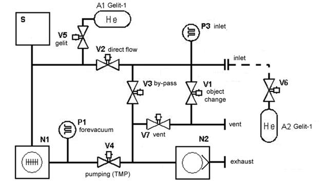
S - mass-spectrometer analyzer
V7 – normally opened electromagnetic valve DN1,6
V1,V5,V6 – normally closed electromagnetic valve DN1,6
V2,V3,V4, – normally closed electromagnetic valve DN1,6
N1 – turbo-molecular pump, N2 - forepump
A1,А2 - helium leak ‘Gelit-1’. The elements V6, and A2 are included in external control leak, which is supplied on request.
P1, P3 – pressure sensors.
Figure 3 - schematic vacuum system of leak detector TI1-50
Evacuating of the tested object is realized by pumping system of leak detector consisting of a forepump (N2) and a high-vacuum turbo-molecular pump (N1). Pre-pumping of the tested object to the working pressure is realized through the valve (V3). The work of leak detector in the ‘counterflow’ mode is realized when the valves V3 and V4 are opened. The work of leak detector in the ‘direct flow’ mode is realized when the valves V2 and V4 are opened. Valve V1 is designed to vent a free air into the tested object when it is changed without stopping the leak detector. Valve V7 is designed to vent a free air when leak detector is turned off or if there is an emergency power failure. Valves V5 and V6 provide connection of control leaks.
Control of inlet pressure is provided by the indicator P3. Control of pressure of the forevacuum line is provided by the indicator P1.
2.5.1 Mass-spectrometer analyzer
The scheme of mass-spectrometer is shown in Figure 4.
The analyzer has a demountable design that provides the opportunity of periodic cleaning and washing. The camera body is a rectangular tube with two flanges. An electrode system is attached to the body flange, mounted on the flange, which has 3 screws for easy removal of the flange during maintenance and repair.

Figure 4 – Mass-spectrometer analyzer
Basic elements of the analyzer:
Leaktight connector of electrometric amplifier (1); gasket of leaktight connector (2); electricity cable of central diaphragm (3); leaktight connector of ions source (5); gasket of leaktight connector (4); electricity cable of cathodes K1, K2 (6); electricity cable of suppressor diaphragm (7); electricity cable of ionization chamber (8); ions collector (9); collector diaphragm (10); suppressor diaphragm (11); inlet diaphragm (12); outlet diaphragm (13); insulating bushings (14); cathode (15); intermediate diaphragm (16).
180-degree angle of the ions rotation in the analyzer and the necessary radius of the trajectory of ions is provided by the location of these elements on the single assembly base – angle bar, attached to the flange (17). The flange, (17) through the gasket, (19) is fixed in the analyzer body (18) with six screws M6.
The ions source consists of two cathodes, the ionization chamber, the outlet diaphragm (13). The cathode is a spiral of tungsten wire welded to the plates-electrodes. The power supply to the electrodes of the ions source and ions collector is realized through seven-pin sealed connector (5).
The analyzer is located in the interpolar gap of the magnetic system with permanent magnets, which provides the magnetic field strength in the range from 0.17 to 0.25 T. The design of the chamber does not require the removal of the magnetic system for maintenance of the analyzer.
2.5.2 Turbo-molecular pump
Turbo-molecular pump is a means of pumping, its operating principle is based on the difference of probabilities of gas molecules passage forward and backward through the slanted grooves of the rotor (turbine), rotating at high speed. In order to increase the degree of compression and expansion of the range of allowed inlet pressures of leak detector to greater values, the pump is additionally equipped with a viscous pumping stage (Holvek’s stage). The controller integrated into the turbo-molecular pump (for the model TI1-50) located next to the TMP near the side wall of the device (for the model TI1-50-01) controls the turbo-molecular pump operation. DC (direct current) provides the power supply of the controller. The controller is built in the leak detector control system and doesn’t require any additional settings.
2.5.3 The valves
In the leak detector, three types of electromagnetic valves, with a flow diameter DN 1.6 (normally opened and normally closed) and DN25, are used. Normally opened valve DN 1.6 (Figure 5) is used to vent air into the forevacuum line (to the pump inlet N2) when power is turned off. This operation is done automatically when the pump is disconnected. It is also necessary to prevent the oil overflow by the atmospheric pressure from the pump case into the vacuum system when it stops. Normally closed valves DN 1.6 (Figure 6) are used to vent an atmosphere on the inlet of leak detector in order to change the tested object, as well as for connection and disconnection of calibrated leaks during setup and calibration of device.

1- valve body, 2- rod of magnetic circuit, 3- valve anchor, 4- return spring, 5- solenoid, 6- gasket
Figure 5 - Normally opened valve DN 1.6

1- retaining ring, 2- solenoid, 3- magnetic circuit, 4- rod, 5- gasket, 6- return spring, 7- plate, 8- valve
Figure 6 – Normally closed valve DN 1.6
For the vacuum system switching at various operating modes electromagnetic valves DN25 (Figure 7) are used. The valves DN25 have two modes of operation: switching-on mode and hold mode. In the switching-on mode, there are 3.5 A current pulse and 200 V with a duration 15-20 ms (forcing) at the valve coil. After the valve switching-on operating DC voltage with a value of 24 V at 0.3 A is applied to the coil winding. This scheme decreases the overheating of the power coil winding, at keeping the valve opened for a long time in the process of operation. Valve operation unit is used for control of valves in leak detector by the commands of the leak detector operating system.

1- retaining ring, 2- solenoid, 3- gasket, 4- anchor, 5- valve body, 6- holder, 7- return spring, 8- sylphon, 9- gasket, 10- valve body
Figure 7 - Valve DN25
2.6 Construction of leak detector
The leak detector is mounted on the aluminium framework. The device rigidity is provided with application of T-shaped bars and welding of the framework elements. An access to elements of vacuum system and units of a control system is provided after removal of the covering panels.
The vacuum system is made from the standard elements connected by means of quick-split connection of ISO KF type. Connection of a high-vacuum part of the leak detector consisting of the analyzer and the turbo-molecular pump, is provided by means of bolt joints and rubber gaskets. The design allows to dismantle the vacuum system for a preventive maintenance without use of special tools and provides a high level of consolidation of the system elements. The arrangement of elements of the vacuum system and of its main units is shown in Figure 8-12 (the covering panels are removed)

1- electrometric amplifier, 2- pressure sensor Р3 passage, 3- sensor P3, 4-magnetic system polar tip, 5-transformer T1, 6-V5 valve (by-pass), 7- pressure sensor Р1 passage, 8-V7 valve, 9-forepump.
Figure 8. The leak detector front side arrangement.

1,15-quick-split connections DN25, 2- sylphon of the turbo-molecular pump; 3- fastening screws of the turbo-molecular pump, 4- magnetic system adjusting screw, 5- magnetic system fastening screw, 6- magnetic system fastening frame, 7- analyzer flange, 8- analyzer flange fastening screws, 9-connector of the analyzer power supply, 10-control leak ‘Gelit-11’, 11-tube of the vent line, 12-V1 valve (object change), 13-tube of the V7 valve, 14-V5 valve.
Figure 9. The leak detector back side arrangement.

1- inlet leak detector flange, 2- turbo-molecular pump, 3- controller of the turbo-molecular pump operation board (in version TI1-50 is not applied), 4- connector of the turbo-molecular pump cooling fan (in version TI1-50 is not applied), 5-V5 valve of the built-in control leak, 6-outlet flange of the turbo-molecular pump, 7- check screws of side panels fastening, 8- oil level of the forepump observation porthole (the other-side placement of the forepump is possible), 9-V2 valve of a direct flow switching.
Figure 10. The leak detector right side arrangement.

1- valve control, 2- adjusting screws of the magnetic system, 3- fastening screws of the magnetic system, 4- pole tips of the magnetic system, 5- analyzer power supply, 6- connection unit, 7- engines and valves control board.
Figure 11- The leak detector top side arrangement.

1- opto-relays of forepump control, 2- external forepump connection flange, 3-pulse supply source 12 V 25 W, 4- vent line tee (if external forepump is installed, under the contract, is not supplied), 5- pulse supply source of turbo-molecular pump 24 V 100 W, 6- supply-line filter, 7- pulse supply source 24 V 25 W, 8- ground bus, 9- connection block.
Figure 12- The leak detector bottom arrangement.
2.7 Scheme of electrical connections
Basic electrical circuits for leak detector TI1-50 are represented in Figures 13 and 14.

Figure 13- Electrical circuit of leak detector TI1-50 version
 Figure 14- Electrical circuit of leak detector TI1-50-01 version
The electrical circuit of leak detector contains elements that are combined in the following units: power supply unit consisting of a socket, combined with fuse ‘F1’, the power switch ‘S1’ and supply-line filter ‘Z1’; unit of pulse power supply sources, consisting of source ‘A19’ - providing turbo-molecular pump power supply, source ‘A20’ - providing power supply of leak detector control system, as well as source ‘A21’ - providing analyzer power supply.
Transformer T1 - forms trigger valve voltage of vacuum system.
The coupling element ‘A2’ - is a cross-board of internal connection bus RS-485.
Analyzer power supply unit ‘A3’ provides formation of supply voltage of the analyzer. It is controlled from board A1 by internal bus RS-485.
The engines and valves control board ‘A4’ - provides formation of valves control commands DN1.6 that do not require forcing supply voltage: ‘V1’, ‘V5’, ‘V7’, ‘V6’, by the turbo-molecular pump ‘M2’, by the opto-relays ‘K1’ of the forepump ‘M3’ power supply control. It is controlled from board A1 by internal bus RS-485.
The valves control unit ‘A5’ - provides formation of valves DN25control commands that require high voltage forcing for the opening: ‘V2’, ‘V3’, ‘V4’. It is controlled from board A1 by internal bus RS-485.
Pressure passage transformer ‘A6’ - provides the power supply of pressure sensor ‘A16’ and converts its signal to a serial format RS-485 of the internal control bus.
Pressure passage transformer ‘A7’ - provides the power supply of pressure sensor ‘A17’ and converts its signal to a serial format RS-485 of the internal control bus.
Electrometric amplifier ‘A8’ - amplifies a ion current of the mass- spectrometer analyzer collector and its transforms into a serial format RS-485 of the internal control bus.
The control and display board ‘A1’ contains control and indicator units, memory module and the central processor of the system. This board controls all boards of leak detector by internal bus RS-485. The external control units are also connected to the board ‘A1’: ‘PC’ connector, for the leak detector external control (e.g. from a PC), ‘Remote Control’ designed to connect the remote control.
3. Leak detector operation
3.1. Operational restrictions
The sensitivity of leak detector and of leak detection control system (with a connected tested object, connection fittings, etc., to the leak detector) depends on the background concentration of helium in the atmosphere of the tests rooms and may be different. This dependence is especially evident when the leak detection methods associated with sampling from the environment (for example, the probe method) are used. Leak detector must be operated in a room that has no external helium sources which are not provided by the technological process or by the testing procedure method. Certificate leak detector sensitivity can be achieved only if the helium density in the atmosphere of the test room does not exceed the normal value for the open air, equal to 5 ppm (5 ∙ 10-4%).
Objects tested by the evacuation method should have a sufficient mechanical strength and to withstand an atmospheric pressure. Objects tested by high pressure test with helium should have a sufficient mechanical strength and withstand an excessive pressure of the tracer gas mixture.
Attention! To avoid bearings damage of the turbo-molecular pump because of the arising gyroscopic moment on the rapidly rotating rotor the leak detector transportation in the ON state is prohibited. During transportation of switched off leak detector equipped with a rotary-vane pump, the inclination of the device exceeding 30 degrees is not allowed. Leak detectors should be placed on a horizontal surface during operation.
Read this manual carefully before starting work and carry out preparatory works referred to in ‘Preparation for work’ section.
If the leak detector has been in a relative humidity exceeding allowable working values, it is necessary to keep it in normal conditions for at least 24 hours before switching it on. If the leak detector was at negative temperatures it is necessary to keep it under normal conditions for at least 8 hours.
The connection of the leak detector to the power supply 220V, 50Hz should be done only through the socket, equipped with a protective earth contact.
The rooms for leak detector testing and storage must be free of dust, chemically active substances and others harmful contaminants that can cause corrosion of components.
3.2 Preparation for work
Before the leak detector installation, make sure that there are no damages of the package. If the leak detector in a package was stored or transported at negative temperatures it is necessary to keep it in normal conditions for at least 8 hours. To avoid leak detector damaging during transportation, forepump is supplied separately in separate package.
Preparation for work of leak detector with an internal forepump (installed inside the device) is realized in the following order:
- unpack the leak detector and the pump, check the compliance of the package contents with the parts list (Table 3). Check the leak detector and the pump for damages.
- install the leak detector at the working place, providing easy access from all sides.
- remove the protective film from the screen surface without using sharp objects.
- remove the cap from the inlet flange of the leak detector.
- remove the top cover by removing four screws (two on each side), located in the hollows of side handles.
- - remove the right and left side panel by loosening eight set (check) screws, four of which are located at the corners of the frame under the top cover, two - on the bottom of the body at the front side and two on the bottom of the body at the back side of the leak detector (in the feet area). Loosening of the set screw allows to take out the side panels with the pins installed on them.
- remove the front panel by unscrewing the screws, located on its inner side.
- fill the pump with oil according to the instructions.
- mount the pump on the tray. Make sure that the pump moves freely on the dampers, without touching the frame.
- remove transportation ties fixing the position of the power cord and inlet sylphon and the pump exhaust hose, in the leak detector body.
- remove the clamp and the transportation cap from the sylphon of forepump. The clamp and the sealing ring are used for connection of the pump to the leak detector vacuum system.
- connect the power cord and outlet hose to the pump. The power switch on the pump body (if available) must be set to ‘I’ position.
- mount the front panels, then the side panels, avoiding any inclinations. Fasten the panel pins with check screws and mount the top cover.
- put the cap on the leak detector inlet.
Preparation of the leak detector for work with an external forepump is realized in the following order:
- unpack the leak detector, the trolley and the pump, check the compliance of the package contents with the parts list (Table 3). Check the leak detector and the pump for damages.
- mount the handle on the trolley and fasten it with the screws (included in the package).
- remove the transportation fastening elements and remove the tray from the trolley.
- mount the pump on the tray and remove the cap on the inlet flange of the pump.
- fill the pump with oil included in the pump delivery set (during the installation of oil forepump), according to the pump operation instructions.
- install the oil vapor trap on the pump exhaust (if the trap is included in the package contents) according to the trap label instructions.
- remove the top, side and front panels of the leak detector according to the instructions for the leak detector with an inner forepump.
- install the leak detector on the trolley and fix it with clamps (included in the trolley package contents).
- install the sylphon (included in the trolley package contents) with a gasket and a clamp on the flange connection of an external pump, passing the sylphon through the hole of the trolley top panel and the leak detector bottom.
- install the sylphon on the forepump flange with a gasket and a clamp.
- connect the pump power cable to the jack ‘Ext. FP’on the panel for external devices (Figure 15), passing it through a hole in the back of the trolley. The power switch on the pump body (if available) must be set to ‘I’ position.
- fix the earthing wire from the pump body to the grounding point situated below the hole for the pump power supply in the back of the trolley.
- mount the front, then the side panels, avoiding inclinations. Fasten the panel pins with check screws and mount the top cover.
- install a cap on the leak detector inlet or connect its inlet to the tested device.

1- circuit cable connection unit with fuse and power switch, 2- power cord jack of the external forepump, 3- nameplate, 4- jack of an external PC, 5- jack of the remote control, 6- jack of a cable of the external control leak, 7- jack of the of external valve power supply, 8 - connection port of the exhaust line. Can be connected to an external ventilation line with polymeric hose with an outer diameter of 8 mm, 9 - connection port of the purified gas line for the the forepump inlet vent, and for the tested object. If there is no purified gas source, install a filter included in the SPTA kit (§ 2.18).
Figure 15 - The appearance and the function of the panel for external devices connection.
3.3 Control panel
The control of leak detector is realized with a quasi touch-control switchboard, as well as rotating encoder handle in combination with a screen menu. To validate the input data press the encoder handle (ENTER function). One group of the keys with their LED indicators is located on the mimic panel figure in the left side of the front panel and is designed to control the vacuum system in manual mode (except for the button ![]() which allows to enable or disable the active cathode in the ready mode of leak detector, as well as buttons
which allows to enable or disable the active cathode in the ready mode of leak detector, as well as buttons ![]() and
and ![]() that allow to control valves of built-in and external leaks during the vacuum tests). Indicators provide a visualization of the state of the vacuum system in manual and automatic mode. The second group of keys and an encoder handle are located on the right side of the panel and are designed to control the most important and frequently used functions of the leak detector (start/stop tests, object change, background compensation).The keys start / stop, as well as background compensation have a light indication of the state. In case of pressing the locked buttons, the acoustic radiator (situated on the print board under the control panel) makes a sound to report an error.
that allow to control valves of built-in and external leaks during the vacuum tests). Indicators provide a visualization of the state of the vacuum system in manual and automatic mode. The second group of keys and an encoder handle are located on the right side of the panel and are designed to control the most important and frequently used functions of the leak detector (start/stop tests, object change, background compensation).The keys start / stop, as well as background compensation have a light indication of the state. In case of pressing the locked buttons, the acoustic radiator (situated on the print board under the control panel) makes a sound to report an error.
The design of the keyboard and the functions of control units is represented in Figure 16.

1- Start/Stop button (СТАРТ/СТОП)
2- Start/Stop button indicator
3- Zero button (НОЛЬ)
4- Zero button indicator
5- Menu button (МЕНЮ)
6- Two-position encoder handle
7- Manual mode indicator (РУЧНОЙ РЕЖИМ)
8- Leak indicator (ТЕЧЬ)
9- Object change button (СМЕНА ОБЪЕКТА)
10- Color graphic display
11- Valve Vent button and indicator (НАПУСК)
12- External leak valve button and indicator
13- Forepump N2 button and indicator
14- Valve V3button and indicator
15- Valve V2 button and indicator
16- Valve V5 button and indicator
17- Valve V4 button and indicator
18- Pump N1 (TMP) button and indicator
19- Cathodes state button and indicators
Figure 16 - The leak detector control panel design.
The functions of control and indication units:
MENU button - ![]() - provides the graphical interface displays changes. User settings interface is displayed by means of the MENU button and password input. Password is input with the encoder handle. A necessary character from the display list is chosen by rotating the handle; the handle pressing confirms the input of the selected character).
- provides the graphical interface displays changes. User settings interface is displayed by means of the MENU button and password input. Password is input with the encoder handle. A necessary character from the display list is chosen by rotating the handle; the handle pressing confirms the input of the selected character).
ZERO button - ![]() - provides the dependance between the current signal value and its background value (dynamic background compensation). ZERO button is active during the vacuum test cycle, only if the type of dynamic background compensation is used.
- provides the dependance between the current signal value and its background value (dynamic background compensation). ZERO button is active during the vacuum test cycle, only if the type of dynamic background compensation is used.
In the process of the automatic configuration / calibration, this button is locked.
START / STOP button - ![]() - starts or stops the vacuum tests cycle in the automatic mode, and interrupts the current cycle of the automatic ajustment / calibration without saving the results. In manual control mode, this button is locked.
- starts or stops the vacuum tests cycle in the automatic mode, and interrupts the current cycle of the automatic ajustment / calibration without saving the results. In manual control mode, this button is locked.
Button OBJECT CHANGE - ![]() - stops the the vacuum tests cycle and the atmosphere venting onto the leak detector inlet and the tested object. In manual mode, this button is locked.
- stops the the vacuum tests cycle and the atmosphere venting onto the leak detector inlet and the tested object. In manual mode, this button is locked.
The mimic panel control buttons:
Active only in manual control mode, except for the buttons S, V5 and V6.
Button V1- ![]() – controls the valve ‘OBJECT CHANGE’. State of the valve is indicated by green color next to the button. Active only in manual control mode.
– controls the valve ‘OBJECT CHANGE’. State of the valve is indicated by green color next to the button. Active only in manual control mode.
Button V6 - ![]() - connects the external leak during the leak detector calibration. State of the valve is indicated by green color next to the button. Active in manual and automatic control modes.
- connects the external leak during the leak detector calibration. State of the valve is indicated by green color next to the button. Active in manual and automatic control modes.
Button V5- ![]() - connects the built-in leak during the leak detector calibration. State of the valve is indicated by green color next to the button. Active in manual and automatic control modes.
- connects the built-in leak during the leak detector calibration. State of the valve is indicated by green color next to the button. Active in manual and automatic control modes.
Button V2- ![]() – controls the direct flow valve. State of the valve is indicated by green color. Active only in manual control mode.
– controls the direct flow valve. State of the valve is indicated by green color. Active only in manual control mode.
Button V3- ![]() – controls the pre-pumping valve and the counterflow mode. State of the valve is indicated by green color. Active only in manual control mode.
– controls the pre-pumping valve and the counterflow mode. State of the valve is indicated by green color. Active only in manual control mode.
Button V4- ![]() – controls the pumping valve of turbo-molecular pump. State of the valve is indicated by green color. Active only in manual control mode.
– controls the pumping valve of turbo-molecular pump. State of the valve is indicated by green color. Active only in manual control mode.
Button N1 - ![]() – controls the turbo-molecular pump. Its state is indicated by dichromatic indicator. In normal mode (the pump functions properly and operates at work frequency of rotation) the green indicator lights up; if some fault happens, the red indicator lights up.
– controls the turbo-molecular pump. Its state is indicated by dichromatic indicator. In normal mode (the pump functions properly and operates at work frequency of rotation) the green indicator lights up; if some fault happens, the red indicator lights up.
Button N2- ![]() - provides a synchronous control of forepump and its vent valve V7. The pump ON state corresponds to the closed valve state, the green indicator lights up.
- provides a synchronous control of forepump and its vent valve V7. The pump ON state corresponds to the closed valve state, the green indicator lights up.
Button S ![]() – controls the analyzer cathodes. In the standby mode the successive pressings of this button enable and disable the active cathode (in kilter of both cathodes it is a cathode 1, if the cathode 1 is off kilter, the cathode 2 will be active). During the vacuum tests in automatic mode, this button is locked. In manual mode the operator can switch the cathodes or shut-down both of them by their successive pressing. In order to improve the usability, the mode of cathodes cyclic switching by the button S pressing is deactivated when the currently working cathode remains switched on for more than 30 seconds. The ON state of kilter cathode is indicated by green color. If a fault happens, the indicator lights up in red.
– controls the analyzer cathodes. In the standby mode the successive pressings of this button enable and disable the active cathode (in kilter of both cathodes it is a cathode 1, if the cathode 1 is off kilter, the cathode 2 will be active). During the vacuum tests in automatic mode, this button is locked. In manual mode the operator can switch the cathodes or shut-down both of them by their successive pressing. In order to improve the usability, the mode of cathodes cyclic switching by the button S pressing is deactivated when the currently working cathode remains switched on for more than 30 seconds. The ON state of kilter cathode is indicated by green color. If a fault happens, the indicator lights up in red.
The indicators LEAK are designed for visual indication of the fixed spoilage threshold being exceded by the current signal level, that considerably facilitates the operator’s work during the stream-handling product verification in industrial conditions. The flashing red light corresponds to a signal exceeding the spoilage threshold, the green indicator light - the signal is below the threshold.
The MANUAL MODE indicator is red when the manual mode is switched on and is designed to increase the operator's attention at work in this potentially unsafe mode.
3.4 Software
The software is installed by the manufacturer and may be upgraded. The version number of installed software is displayed after the leak detector power is switched on.
The Central Board controls a number of peripherals (modules) on the internal bus RS485, providing a high leak detector maintainability in case of some modules fault. These peripheral modules are:
- valve control unit that provides the power supply of valves requiring the power chain forcing at the moment of opening;
- analyzer power unit that provides the normalization of the necessary electrical signals for the mass spectrometer ions source;
- the engine and valves control board that provides the control of valves DN 1.6 (do not require the electric forcing), of the opto-relays of switching on the forepump and of turbo-molecular pump controller;
- the pressure passage amplifiers supporting the pressure sensors P1 and P3 electrical mode, as well as their signals processing ;
- electrometric amplifier, which provides pre-processing of the signal emitted on the ion collector of the mass-spectrometer cell.
The control system allows to set an automatic or manual testing mode and provides the parameters settings necessary for correct operation. Leak detector settings that influence the control system efficiency, as well as the transition to the manual control mode are protected with a password.
The default password is: AAA.
To prevent unauthorized access to leak detector password-protected settings, it is recommended to change the password to the unique symbols combination. The information about the new password must be entered in the device logbook and be available only to the competent service staff.
3.5 Control of settings
Check the position POWER of the switch. It should be in position ‘0’. Connect the cord to the block on the back of the leak detector. Connect the plug to the socket of 220 V, 50 Hz, equipped with a protective grounding contact.
The leak detector switching on
Set the switch POWER on the power block to ‘I’ position.
At the power supply beginning, the control panel display should start working and display the loading window, with the name of the device, the name of the manufacturer and the version number of installed software. At the leak detector start all the elements of the vacuum system are tested. Depending on settings, the cycle of automatic configuration / calibration by built-in leak can also be launched. At the end of switching on, the ready mode ensues; it is indicated by the message ‘Ready mode’ in the status bar at the bottom of the display. During the leak detector start-up and testing its settings can be displayed, so it can be controlled in the manual mode. This opportunity can be used for troubleshooting if the device can’t be brought to ready mode by the automatic control system because of a fault.
3.5.1 Settings menu
The settings menu is used for leak detector parameters settings which determine its functioning in all modes and also contains the settings which need not fast changes, i.e. not required during the current cycle of vacuum tests. Depending on the test scheme, parameters of the tested objects, the vacuum tests technological instructions requirements of and others factors, the optimal settings values may vary.
For displaying the settings menu, press the MENU button, then input the correct password. MENU button is unavailable in automatic mode during the vacuum tests conduction as well as during the process of the leak detector automatic configuration / calibration.
The password input display is shown in Figure 17.

Figure 17 - The password input display
Password input procedure:
Press the MENU button. In the right side of the screen, the letter set displays. To choose a character, rotate the encoder handle, highlight the appropriate character and confirm the choice by pressing the handle (ENTER function). Repeat these procedure for all password characters (default password is ‘AAA’). Then set the marker on PASSWORD INPUT field and press ENTER. If the correct password is entered, the screen will display a list of leak detector settings. If the password is incorrect, the message ‘Invalid Password’ will be displayed; the control system will be in a state of the password re-entering. If the password is entered incorrectly three times, an automatic exit from this menu will follow.
To navigate through the menu settings (Figure 18), rotate the encoder handle. The selected menu item is highlighted, and after a short delay, the name of the item will be replaced by the current set value of the corresponding parameter. This feature allows the value of established parameters to be viewed without entering the corresponding menu items. The changing of the current (highlighted) parameter is realized by pressing encoder handle (ENTER). The set value changing is realized by rotating the encoder handle: clockwise - increases the value, anticlockwise – decreases the value. The set value is saved in the memory after pressing the button ENTER.

Figure 18 - Leak detector settings menu
The settings menu has the following parameters:
Manual\auto leak detection - the choice of leak detector mode: automatic or manual control.
Calibration after start - enables or disables the leak detector automatic adjustment/calibration at power switched on.
Switch on counterflow threshold - allows to set the pressure at the leak detector inlet (P3), so that the control system switches the leak detector in the mode of counter flow (at the automatic control mode) or disables the leak detector to switch to counter flow mode at any pressure values at the inlet when the parameter is set to a value ‘no switching to the counterflow.’ The possible range is 5-1000 Pa.
Switch on direct flow threshold - allows to set the pressure at the leak detector inlet (P3), so that the control system switches the leak detector in the mode of direct flow (at the automatic control mode) or disables the leak detector to switch to direct flow mode at any pressure values at the inlet when the parameter is set to a value ‘no switching to the counter flow.’ The possible range is 0,5-20 Pa.
Note: In order to ensure the stability of the leak detector pumping system work, it is not recommended to set the value of switching to the direct flow threshold more than 10 Pa at work with objects of more than 5 liters volume without use of auxiliary pumping equipment.
Measurement Units - measurement setting for displaying the flow and pressure values. It is possible to set the following dimensions: ‘m3. Pa/s – Pa’, ‘micronHg.l/s – mm Hg’, ‘mbar.l/s – mbar’, ‘atm sm3 /s – atm’, ‘mV EA – Pa’. The value of the signal flow in mV EA (millivolts of output voltage of the electrometer amplifier) allows to make the manual calculations of the flow values for solving non-standard test problems.
Maximum time of pump - the setting of the maximum allowed time for the leak detector to be in the pre-pumping mode up to a pressure value making it to switch to the direct flow mode or counter flow mode. Do not set the long duration of the pre-pumping, because the forepump continuous work at a high inlet pressure can lead to increased oil outflow with the flow of pumped gas. The possible range is 1-99 min.
Time of signal integrator - determines the degree of the electrometric amplifier outlet signal smoothing. The increase of this parameter makes it easier to identify the signal on the background of noise and raise the sensitivity level in some cases. The decrease of this parameter reduces the leak detector reaction time, but increases the noise. The possible range is 300-9000 ms.
The cathode in ready mode - specifies the cathode mode (on/off) when the leak detector is in ready mode. The operator can enable or disable the cathode manually in ready mode by pressing the S button. The continious cathode ON state in the ready mode maintenance reduces its lifetime, but accelerates the signal stabilization at transition to the vacuum tests mode, because due to gas emanation during the cathode heating a considerable change of outlet signal level occurs.
STD internal leak value - sets the value of internal leak, installed in the leak detector. The internal leak set value must coincide with the data specified in the certificate of leakage verification. As a rule, this value is indicated on the leak body. At an internal leak value entering the measure units installed in the leak detector settings must coincide with those indicated in the leak certificate.
Calibration temperature - the temperature setting in Celsius degrees, at which the internal flow was verified. This value is indicated in the leak certificate.
Total work time - the parameter indicating the total leak detector operating time. Changing it is impossible. At delivery, the leak detector already has an operating time of a few tens of hours, due to its configuration and its technological running-in by the manufacturer.
Time of leak stabilization - sets the waiting time of the background signal stabilization and of the signal from the external control leak during the automatic calibration by the external leak. This time can vary widely depending on the characteristics of the tested object to which the external leak is connected during the calibration process. The possible values range is 1-400 min. Before the calibration on external leak, it is recommended to determine this parameter for the tested object, by measuring the time when a steady signal is registered after the external control leak (installed at the object) opening. A correct identification and setting of the constant background stabilization time in the leak detector allows to achieve a maximum calibration accuracy by the external leak and to avoid an extra duration of the calibration process due to excessive waiting time of the signal level stabilization.
Control - the leak detector control mode selection: local (from the front panel) or external (from the remote PC or external control system). The work in an external control mode allows to connect the leak detector to the systems of data storage and processing and integrate the device into the automated lines.
The password exchange - after the encoder pressing, the display for entering the new password appears.
The new password input process is similar to this of a password input used for the settings menu displayng.
After entering the new letter password, and after pressing ‘password exchange’, you need to re-type the new password and press ‘confirm password’.
The repeated input of new password makes the incorrect password setting impossible.
Time/Date - calendar and clock setting. Year, month, date, hours, minutes, seconds are selected successively. The current date and time are used at saving and further browsing of measurements results. They don’t influence the information of the device operating time.
3.5.2 Default settings
For acquaintance with the methods of leak detector settings modes, and for specification of the set parameters values, the settings check is carried out.
To check the settings, press ‘MENU’ button, enter the password (the default password is ‘AAA’), consecutively select and input the characters by the encoder handle rotation and confirm the choice by pressing the handle (ENTER function). Then choose the option ‘Enter Password’ and press ENTER. If the password is not correct, there will be a sound signal and the message bar will display ’password is incorrect’, then you can re-enter the password.
On the settings entry display, check the values of default settings in the range specified in the Table 5, select consecutively the appropriate menu items by rotating the handle; in 1-2 seconds, instead of the item name the current value will be shown. If it is necessary to change the default settings, select a required menu item and press ENTER, then change the set values by rotating the handle; to confirm the setting changes, press ENTER.
Table 5
|
Item |
Value range |
Default setting |
Note |
|
Calibration after start |
On/Off |
Off |
|
|
Transition to the counter flow threshold |
0,1-1000 Pa/ Counter flow is prohibited |
500 Pa |
|
|
Transition to the direct flow threshold |
0,1-20 Pa/ Direct flow is prohibited |
5 Pa |
|
|
Measurement unit |
m3.Pa/s (Pa); mm.hg..l/s(mm Hg);
|
m3. Pa/s (Pa) |
|
|
Maximum pumping time |
1-99 min |
10 min |
|
|
Signal integration time |
300-9000 ms |
1500 ms |
|
|
Cathode in ready mode |
On/Off |
On |
|
|
Internal leak value |
1.10-7 -9,9.10-9 m3. Pa/s |
Complies with the value specified in the internal control leak certificate |
|
|
The verification temperature, ºС |
15-35 ºС |
Complies with the value specified in the internal control leak certificate |
|
|
Operating time |
Complies with the current operating time resulted from the technological running-in by the manufacturer |
- |
|
|
The time of background signal stabilization |
1-400 min |
1 min |
|
|
Control |
Local/External |
Local |
|
|
Password exchange |
from 1 to 14 characters |
AAA |
It is recommended to change a password at the first usage |
|
Time/Date |
- |
Current time |
Install a local time |
To leave the settings entry display, press ‘MENU’ button (for return to either automatic or manual mode), or select the menu item ‘Manual / Automatic mode’. Select the desired mode by rotating the encoder handle and press ‘ENTER’.
3.6 Operating modes
The control system provides the leak detector operation in two modes: automatic and manual ones. To carry on everyday activities, it is recommended to use the automatic mode. The manual mode is used mainly for non-standard work, as well as for repair and adjustment, so it should be practiced with caution and only by qualified personnel.
3.6.1 Automatic mode
The is the basic operation mode. The leak detector control system passes to the default automatic mode just after the power is turned on. This is a safe mode because an operator can’t make any damage to leak detector by wrong actions. The control system monitors the state of all elements and blocks any unsafe actions. The automatic control mode maintains the following main phases:
The leak detector work start.
After switching on the toggle POWER SUPPLY situated on the leak detector back panel, the loading window is displayed. It shows the type of device, the manufacturer name, and the software version. Then the automatic launch of the vacuum system elements is initialized, resulted by the leak detector readiness for the vacuum tests. If the leak detector settings provide a passage to the automatic configuration/calibration after switching-on, the process of automatic configuration/calibration by the internal leak is carried out additionally (regardless of the external leak connection to the appropriate junction). During the leak detector start-up and testing, it can be switched to a manual control mode by pressing ‘MENU’ button. It can be used for troubleshooting if the automatic control system cannot ensure the transition to the ready mode because of some malfunction.
Ready state.
State from which the process of automatic vacuum tests can be started. In this state: N1 is accelerated to the normal speed, N2 is ON, V4 is opened. The current cathode can be switched off or on, depending on the leak detector settings. The operator can also enable or disable the current cathode by pressing S button. If long operation downtimes occur it is recommended to disable the cathode, in order to preserve its lifetime length. The automatic control mode is displayed. The leak detector can stay in this state for unlimited time, waiting for operator’s further actions.
Wait state.
An automatic control system puts leak detector in this state after an error, non-critical for its operability occurs. However, the error may influence its normal performance (e.g. in case of the automatic configuration / calibration process failure). The leak detector state is identical to this of readiness, but START / STOP button is locked, so the vacuum tests cycle cannot be launched before debugging. The status bar displays an error message. The leak detector can stay in this state for unlimited time, waiting for trouble-shooting.
Stop state.
An automatic control system puts the leak detector in this state after an error, critical for its operability occurs. In this state, all the vacuum system elements are disabled. The status bar displays an error message. Only MENU button is available. It provides an access to the leak detector settings or to the manual mode, for trouble-shooting.
Object changing.
This mode is designed to vent the atmosphere to the leak detector inlet in order to change the tested object. Operator activates it from the Ready state, or from vacuum tests, or from Wait state, by pressing CHANGE THE OBJECT button. If this button is pressed at the vacuum tests mode, the test mode will be interrupted. The vent valve is opened until P3 value equal to the atmospheric pressure is reached, then V1 is automatically closed and the leak detector will be switched to the Ready state.
Automatic adjustement / calibration by the internal leak.
The mode is designed for automatic adjustment/calibration of the leak detector mass-spectrometer to the registration of the tracer gas (helium) by changing the accelerating voltage within the small limits. As a result, the new value of the accelerating voltage providing the maximum signal value from the internal helium leak, is recorded in the leak detector memory. Simultaneously, the measuring scale calibration takes place, which allows the value of the specified signal to be compared with the flow measurement units fixed in the settings. It is recommended to carry out from time to time the automatic adjustment / calibration during operation (especially when the external conditions – temperature, humidity, etc. vary). Thus the analyzer setting correctness, therefore, a maximum device sensitivity are provided. To interrupt the current cycle of the automatic calibration, cancel its results and put the leak detector in the Ready mode, press START / STOP button. Depending on the leak detector settings, this mode can be started up automatically during the first switching on, regardless of whether the external leak valve is connected to the circuit. When the automatic adjustment / calibration is finished, the reached value of the minimal detectable flow by the internal leak is recorded in the leak detector memory, and the device switches to the Ready mode.
The minimal detectable flow check.
The check is realized from the leak detector automatic control screen.
Start the adjustment / calibration by the internal leak by selecting ‘Calibration Manual / Auto’ and press ‘ENTER’, then select ‘internal autotuning’ by rotating the encoder and start the process by pressing ‘ENTER’. During the autotuning, the analyzer output signal curve is displayed, having the typical shape of inverted parabola (symmetric, as in Fig. 19, or asymmetric), with a prominent maximum. If there is no prominent maximum, restart the automatic adjustment / calibration by the internal leak. The specified form of the curve indicates the correctness of autotuning and the analyzer operability. After the adjustment / calibration is finished, the value of the minimal detectable flow with the fixed dimensions should be displayed. The minimal detectable flow should not exceed the passport value. If the minimal detectable flux exceeds this value, it is necessary to carry out the adjustement of the analyzer magnetic system.
Note. The value of the minimal detectable flow in the counter flow mode during the process is constructively related to the value of the minimal detectable flow in the direct flow mode through the correction coefficient (set by the manufacturer) and is not checked separately.

Figure 19 – Analyzer autotuning to the helium peak
The automatic calibration by the external leak.
This mode is similar to this by the internal leak, however, there is no analyzer autotuning to the helium peak. It can be started in the ‘probe’ mode, or a in the universal mode if an assembled external leak (available on request) is electrically connected to the joint ‘EXT. FLOW’ on the leak detector back panel. The main calibration by the external leak purpose is: to increase the accuracy of leaks estimates in the real tested objects (especially those of large volumes or having an extra gas loading). The external factors, varying widely, can in certain cases considerably distort the accuracy of leak detector indications if it is calibrated by the internal control leak only. It is necessary to take into account that, to achieve the most exact correspondence of leak examination results to the real flow value, it is necessary to carry on the leak detector calibration by the external leak. The detected leak location and the operating mode during the calibration by the reference leak, as well as the further examined leak observation, should be as identical as possible. For example, the use of leak detector calibration results by external leak in the counter flow mode is absolutely inapplicable for estimates of leaks values in the direct flow mode. It is recommended that the operator, during the calibration by the external leak, determines consecutively a minimal detectable flow for both modes (counter flow and direct flow ones). Later, during the automatic vacuum tests, the modes in which the calibration is not successful, or not done will be blocked.
Manual calibration by external leak.
At the lack of a controlled external leak, a manual calibration by external leak can be done. This calibration is similar, with the exception that the external leak is opened and closed manually; the moment when it is necessary to open or to close a helium leak is displayed in the message bar.
The calibration of mode with accumulation.
The obligatory conditions for selection of the mode with accumulation are the external controlled leak and operation in direct flow. The leak detector will automatically control the external leak by accumulating first the background (in a given accumulation interval), then the helium flow of standard leak (for the same time interval), with a calculation of the minimal sensitivity after the accumulation and of the sharpness of the signal growth.
The calibration of mode with the probe.
This calibration is possible after the leak detector is switched to PROBE mode. This action doesn’t depend on the external leak item connection/disconnection to the leak detector, because the probe calibration is carried out by the external control capillary leak. In this case, during the calibration, the leak detector control system sends to the operator requests to supply or to stop the tracer gas from the leak to the probe (the process is similar to the manual calibration by external leak).
Vacuum tests with dial switching of the leak detector vacuum system.
This mode is started with button START/STOP from the automatic mode screen. The repeated button pressing stops the mode and switches the leak detector to ready state. The mode can be also interrupted with button OBJECT CHANGE or automatically, by the leak detector control system in case of some faults. In automatic mode of vacuum tests all interlocks, designed in leak detector, are active. This mode can be realized in three variants – with or without accumulation, and probe (their description is given further).
Automatic mode of vacuum testing without accumulation includes 3 phases (states of leak detector):
- pre-pumping of the tested object. The mode is used for pressure reduction at the leak detector inlet up to the counterflow threshold (or the direct flow at once, if operation in counter flow mode is prohibited by leak detector settings or by negative results of the previous calibration by external leak, or the inlet pressure allows to switch the leak detector to the direct flow mode). In this mode, the analyzer cathode is turned on (if it is previously turned off), analyzer is pumped by pump N1, valve V4 is closed, V3 is opened. The system provides pumping off the leak detector inlet, with a vacuum testing object connected to it, up to a pressure when leak detector switches to the counter flow (or direct flow) mode. For maintaining a sufficient vacuum value at the turbo-molecular pump outlet in the process of long-term pumping off of the external object, the system provides periodical closing of V3 and opening of V4. The total time of pre-pumping before pressure P3 reaches the counterflow threshold (or direct flow) should not exceed maximum duration of pumping-off, set in leak detector settings. The minimum duration of staying in pre-pumping mode is 10 s;
- counter flow mode. In this mode, the countercurrent flow scheme of vacuum tests signal value is registered. The analyzer is pumped off by pump N1through the valve V4. The valve V3 is open, providing leak detector inlet pumping off, as well as that of pump N1 by means of pump N2. The transition to this mode (if it is not prohibited by the leak detector settings, or by negative results of preceding calibration by external leak in the counterflow mode) from the pre-pumping mode is carried out when the pressure P3 reaches the counterflow threshold. If the maximum value of the flow measurement scale is exceeded by more than 5 s, an automatic turn off of the vacuum test mode occurs, the status bar displays ‘helium poisoning’. The counter flow mode allows to work with higher gas pressures at the leak detector inlet in comparison with the direct flow mode. The counter flow mode is used for detection of leaks with a great helium concentration in of leak sites, for leaks localization by blowing method or probe method.
- direct flow mode. The most sensitive mode. V2 and V4 are open, V3 is closed. The analyzer is connected directly to the leak detector inlet. Switching to this mode is realized during vacuum tests from the counter flow or pre-pumping modes when pressure P3 reaches the switch on direct flow threshold, if the transition to this mode is not prohibited by the leak detector settings, or by negative results of previous calibration by external leak in the direct flow mode. If the maximum value of the flow measurement scale is exceeded by more than 5 s, an automatic transition to the counter flow mode occurs. The direct flow mode is realized through the valve V2. This mode is most widely used for determination of the leakage value of the object by method of vacuum chamber, accumulation, as well as by method of blowing. The direct flow mode is more sensitive in comparison with the counter flow mode and allows to find lower helium concentrations in the tested volume.
Automatic mode of vacuum tests with accumulation is designed for measuring small helium flows, with an increased sensitivity in the direct flow. In this mode, first the background flow, then the helium flow accumulation is carried out by means of timer, during the corresponding time intervals set in the leak detector settings.
This mode includes 3 phases (states of leak detector):
- pre-pumping of a vacuum tested object. This mode is designed to reduce the pressure at the leak detector inlet, up to the switch on direct flow threshold. In this mode, the analyzer cathode switches on (if it was previously turned off), the analyzer is pumped off with the pump N1, the valve V4 is closed, the valve V3 is open; the pumping of the leak detector inlet with a vacuum testing object connected to it, up to a pressure when leak detector switches to the direct flow mode.
For maintaining a sufficient vacuum value at the turbo-molecular pump outlet in the process of long-term pumping off of the external object, the periodic closing of V3 and the opening of V4 is done. The total time of pre-pumping before pressure P3 reaches the directflow threshold should not exceed maximum duration of pumping-off, set in leak detector settings. The minimum duration of staying in pre-pumping mode is 10 s;
- direct flow mode, ‘the background accumulation’. V2 and V4 are open, V3 is closed. The analyzer is directly connected to the leak detector inlet.
Switching to this mode is realized during vacuum tests from the pre-pumping mode when pressure P3 reaches the switch on direct flow threshold, and if the transition to this mode is not prohibited by negative results of previous calibration by external leak in the direct flow mode. The direct flow mode is realized through the valve V2. The external object, in this case, is usually the vacuum chamber. Direct flow mode is realized through the valve V2. After background is stabilized, the command ‘Start accumulation’ – ‘Background accumulation’ starts the background accumulation in the chamber. Valve V4 closes and, if there is control, the external chamber pumping turns off. The background accumulation is completed after a time interval defined in the leak detector parameters as ‘accumulation time’. The valve V4 and the external pumping open.
- direct flow mode, ‘the helium accumulation’. The tested object is exposed to the helium influence by means of blowing or another way; the accumulation start is activated by pressing ‘ENTER’ on the item ‘Helium accumulation’ (this item appears automatically instead of ‘background accumulation’). The valve V4 closes, and the external pumping is stopped. The helium accumulation is realized and it is completed after a time interval defined in the leak detector parameters as ‘accumulation time’. The valve V4 and the pumping open, the value of the accumulated helium flow is calculated. This value displays until the accumulation process repeats. The accumulation can be done many times during one test cycle.
Automatic testing mode by probe method includes 2 phases (states of the leak detector):
- inlet pre-pumping. This mode is designed for reduction of pressure at the leak detector inlet up to pressure, needed for valve V4 opening. The time of pre-pumping before pressure P3 reaches the counterflow threshold should not exceed maximum duration of pumping-off, set in leak detector settings. The minimum duration of staying in pre-pumping mode is 10 s;
- counter flow mode. In this mode, the counter flow scheme of vacuum tests signal value is registered as in the mode without accumulation, however, there is a difference: during operation in the probe mode, the control of flow is carried out with the probe by measuring of pressure Р3. In case of Р3 pressure decrease below the half of certificate value (for standard versions of leak detectors TI1-50 this value is 30 Pa), the probe is considered to be clogged. The status bar displays ‘probe clogged’, the current testing cycle is interrupted, and leak detector switches to the ready mode, which allows to restart the cycle after probe replacement, without any other additional actions.
Attention: before the tests in the probe mode start, the caps should be removed from the probe.
3.6.2 Operator's work screen in the automatic control mode
The operator's work screen is designed for everyday carrying out similar vacuum tests. When the leak detector is switched on, the control program provides automatic transition to the screen. The menu contains the most important information about leak detector operation (Figure 20).

Figure 20- Operator's work screen in the automatic control mode
- diagram of leakage flow value in units specified by operator. Fragments of the curve, located above the level of the specified rejection threshold are displayed in red;
- numerical expression of leakage flow value, synchronously repeating the value, presented in graph;
- numerical expression of flow average value for all time period shown in the diagram, Qav (only for software version 1.4 and higher);
- numerical values of pressure in leak detector vacuum system (Р1, Р3);
- status bar. This bar displays information about current operation mode, as well as error messages;
- menu of the leak detector express settings, i.e. parameters, which may be necessary for operator to change, for doing some non-specific work, or for perception convenience improvement. The change of this settings does not influence an operation safety and cannot be the cause of device damage or injuries, so there is no need to protect this menu by password. The settings menu navigation is provided by the encoder handle rotation. The selected menu item is highlighted and after a pause, the item name will be replaced by the current set value of a corresponding parameter. This option allows to look through the values of set parameters without entering the corresponding menu items. The change of current (highlighted) parameter is initialized by pressing the encoder handle. The change of set value is realized by rotation of the encoder handle: clockwise – increase of the value, counterclockwise – decrease. A set value is saved in memory by ENTER command.
The express settings menu contains the following parameters.
Leak axes zoom - allows to change the graph scale over vertical axis (flow axis). Clockwise rotation of the handle allows to increase the graph scale, counterclockwise – to decrease.
Time axes zoom - value of this parameter defines the value of time interval in flow graph, which is displayed. The possible range of values is from 30s. to 600 min.
Threshold input - setting of rejection threshold value in current flow measurement units. If the current value of signal exceeds the set value of the rejection threshold, the sound (if it is allowed by the leak detector settings) and light alarms are actuated. Use of rejection threshold for signaling the leak of specified level facilitates the operator work during the serial output control.
Sound indication - this setting provides the sound signal when the rejection threshold is exceeded by the value of current signal. This sound indication facilitates the operator work during the serial output control, especially in conditions of limited visibility. The signal sound pitch depends on the proximity of the current value signal to the rejection threshold. It allows to judge about the signal changing trend (decrease or increase) by sound.
Calibration man/auto – when it is highlighted, the leak detector sensitivity after the last calibration is displayed. After activation of this item by encoder (ENTER), by the encoder rotation either ‘Auto calibration int.’ or ‘Manual calibration ext.’ can be selected. If you select the internal auto-calibration, the calibration by standard internal leak with the closed outlet start. If you select an external manual calibration, the type of operation is requested - in direct flow mode or in counter flow mode (the mode selection is confirmed by pressing the ‘Enter’ button), then the value of the external leak in the selected units is requested, and then, with an encoder starts working, the calibration of an external object begins. After the background measuring, the leak detector pauses for the manual operations of opening of the external standard helium source; after its opening press the encoder ‘ENTER’ button and measure the standard helium flow. When measurement of the standard leak is done, the leak detector indicates its closing requirement.
If the PROBE mode is selected, or an external automatically controlled helium standard source is connected to ‘EXT. FLOW’ on the leak detector back panel, the name of this item is automatically changes to ‘Auto-calibration ext.’. The calibration process for the PROBE mode should be started exactly in the same way as the manual calibration by external control leak (described above), but the difference is that leak switching is realized automatically. In this case, the stabilization waiting time of both background and desired signal is determined by the ‘Stabilization time’ parameters in the leak detector settings.
Archive save/show – allows to save the current testing result (which is displayed) or to display the archive of saved results. The tests results are saved with current system time and date. In order to simplify the further search of necessary data in records archive, it is necessary to set clock and calendar of control system in leak detector settings correctly.
Ua deviation - allows the operator to verify the observed signal, i.e. to make sure that the observed signal is caused by helium ions. Pressing ENTER automatically changes the analyzer accelerating voltage by 3 s. (approximately), making its dispersing relative to the helium peak and allowing to observe the value of the background signal, without taking into consideration the helium ions current influence.
Operating mode – the choice of vacuum tests mode. In the mode ‘without accumulation’, the tests in direct flow and in counter flow are realized depending on the pressure in the object (if these modes are not prohibited in the leak detector settings). The mode ‘probe’ is designed for operating by the probe method, providing an additional comfort and veracity of tests results. This mode has its own semi-automatic calibration by the external leak, allowing to achieve a maximum leakages estimates accuracy during tests, as well as a control of the probe operability, allowing to prevent a clogged probe usage, and to avoid an acceptance of defective products. The probe usage is also possible in ‘without accumulation’ mode, but in this case, the additional functions are not available.
Mode ‘With accumulation’ is intended for small helium flows measurement, with an increased sensitivity in the direct flow. In this mode, the accumulation first of the background flow, then of the helium flow for the leak detector set time interval, by means of the timer, is carried out. The functions ‘Background accumulation’ and ‘Helium accumulation’ are activated in the same menu item after ‘direct flow’ (replacing ‘mode’ item) opening by pressing encoder ‘ENTER’. In each cycle of measurement, the ‘Background accumulation’ and then ‘Helium accumulation’ are carried out. After ‘Helium accumulation’ is completed, the helium flow value, in the selected units, is displayed, this value is shown on the screen before the new measurement cycle start.
In the process of vacuum tests conducted in modes ‘Without accumulation’ and ‘Probe’, the menu command of switching on an automatical (dynamic) background compensation, instead of the item ‘Operating mode’, appears. The compensation is turned off by default, the menu item is called ‘No compensation’. When you press the encoder button (ENTER function), it is possible to enable / disable the dynamic background compensation. When you rotate the encoder handle the name of the menu item changes to ‘Background autocomp.’. After that, the dynamic background autocompensation switches on and the slope coefficient of the visible part of the signal on the graph (during this operation the sections corresponding to the first and the last 5 seconds are excluded from the calculation) is automatically calculated. The obtained value is used to flatten the signal curve caused by the slow alteration of the background level (for example, because of the continued pumping of the object). Selecting the diagram time window you can achieve the most convenient visual display of the signal; it allows to carry out measurements of small signals during the slow background change. The maximum value of the signal for the displayed time interval is the leakage flow value, and it is displayed as a digital parameter Qmax.
3.6.3 Manual mode of leak detector control
For carrying out some non-standard operation, as well as repair and maintenance of the leak detector, it can be switched to the manual control mode. In this mode, in order to avoid hindrances in operator work, all active operations of the automatic system are locked and its functions are limited by displaying the warning messages in case of actions able to hurt the device operability; the control is realized by means of the mimic panel situated on the left side of the control panel. After the system shows a warning message, the operator can confirm the requested actions by pressing repeatedly an appropriate button. Otherwise, the automatic denial of carrying them out is displayed in 5 s (after completion of warning sound signal).
The list of warning messages is given in Table 6.
Attention! Erroneous operator actions during operation in manual mode can lead to the leak detector breakdown followed by the warranty termination.
Table 6
|
Operator action |
Message of control system |
Possible consequences |
|
Attempt to open V1 with opened V2 or V3 |
‘ Close V2 and V3’ |
Direct vent into the vacuum system |
|
Attempt to open V2 or V3 with opened V1 |
‘ Close V1’ |
Direct vent into the vacuum system |
|
Attempt to open V2 with opened V3 |
‘ Close V3’ |
Possible infiltration of dirt from the forevacuum line into the high-vacuum part |
|
Attempt to open V3 with opened V2 |
‘ Close V2’ |
Possible infiltration of dirt from the forevacuum line into the high-vacuum part |
|
Attempt to open V2 at P3>22 Pa (max. threshold of switching to direct flow + 10%) |
‘Р3>22 Pa do not open V2’ |
Deterioration of the vacuum in the analyzer, the cathode burning and overloading of TMP are possible |
|
Attempt to open V4 at opened V3 and P3>1100 Pa (max. threshold of switching to counter flow + 10%) |
‘Close V3-P3>1100 Pa’ |
Deterioration of the vacuum in the analyzer, the cathode burning and overloading of TMP are possible |
|
Attempt to stop N1 at turned on cathode |
‘Cathodes are turned on!’ |
Deterioration of the vacuum in the analyzer and the cathode burning |
|
Attempt to turn on N1 at P1>1100 Pa |
‘Р1>1100 Pa’ |
Deterioration of the vacuum in the analyzer and the cathode burning |
|
Attempt to open V4 at stopped N2 |
‘FVP is not turned on’ |
Vent in the analyzer, the cathode burning, overloading and stoppage of TMP |
|
Attempt to stop N2 at opened V4 |
‘V4 is not closed’ |
Vent in the analyzer, the cathode burning, overloading and stoppage of TMP |
|
Attempt to stop N2 at opened V3 |
‘V3 is not closed’ |
Vent of the leak detector inlet and of the connected object |
|
Attempt to turn on cathode when N1 is not ready |
‘TMP is not ready’ |
Vacuum in analyzer can be insufficiently high, the cathode burning is possible |
|
Attempt to turn on cathode at N1 in operation and P1>1100 Pa |
‘Р1>1100 Pa’ |
Deterioration of the vacuum in the analyzer, the cathode burning is possible |
|
Attempt to turn on the cathode at N1 in operation, V2 is opened and P3>22 Pa |
‘Р3>22 Pa and V2 is opened’ |
Deterioration of the vacuum in the analyzer, the cathode burning is possible |
3.6.4 Operator working screen in manual control mode
It is designed for carrying out vacuum tests that require non-standard leak detector operation modes, as well as the leak detector maintenance and repair by qualified personnel.
The screen appearance is similar to that in automatic mode, but in the manual mode it displays the greater number of parameters that can be used during complex operations (see Figure 21). Opening of the settings screen from the manual control mode is done similarly to opening the automatic control screen by pressing MENU button (there is no need to input password). The screen contains:

Figure 21- Operator working screen in manual control mode
- diagram of leakage flow value in mV. Fragments of the curve, located above the level of the specified rejection threshold are displayed in red;
- numerical values of main parameters of observed signal for the period, represented in the diagram field: maximum value of signal (Umax), minimum detectable flow obtained as a result of autotuning (Qmin), average value of signal (Ucp), value of signal fluctuation (dQ), value of the rejection threshold (Qth);
- numerical pressure values in the leak detector vacuum system (Р1, Р3) in units set by operator;
- status bar. This bar displays information about current operation mode, as well as error messages;
- menu of the leak detector express settings, i.e. parameters, which may be necessary for operator to change, for doing some non-specific work, or for perception convenience improvement. Functions of express-settings menu of manual mode screen are fully identical to those of automatic mode screen, but the set of changeable parameters slightly differs.
Menu of express settings contains the following parameters:
Leak axes zoom - is used similarly to automatic mode screen;
Time axes zoom - is used similarly to automatic mode screen;
Threshold input - is used similarly to automatic mode screen;
Sound indication - is used similarly to automatic mode screen.
Ua deviation - allows the operator to verify the observed signal, i.e. to make sure that the observed signal is caused by helium ions. Pressing ENTER automatically changes the analyzer accelerating voltage by 1 s. (approximately), making its dispersing relative to the helium peak and allowing to observe the value of the background signal, without taking into consideration the helium ions current influence.
Archive save/show - used similarly to automatic mode screen;
Supressor U - allows to change the voltage value, applied to suppression diaphragm of the analyzer ion collector. A suppression voltage changes in some cases allow to obtain some increase of the desired signal caused by helium ions related to the noise signal ratio. The noise signal is produced by secondary particles, generated as the result of interaction between the ion beam and gases present in residual atmosphere of the analyzer chamber. Possible values range is 10-300 V;
Anode U - allows to change the value of accelerating voltage of ion source in the mass-spectrometric analyzer, which defines its configuration for tracer gas ions registration (helium). Change of this parameter allows to configure analyzer manually without control system usage. Possible values range is 10-500 V.
3.7 Archive screen
Archive screen (Figure 22) is designed for viewing, as well as deleting of saved testing results. Opening of the archive screen is realized through the menu of express settings in the screen of automatic or manual control mode.

Figure 22- Archive screen
The left side of the screen contains the list of saved testing results, sorted by date and time of saving (the latest records are located at the top). The right side of the screen contains a menu of previously made operations, which consists of the following items.
Return to measure mode - ENTER pressing allows to return to the screen of the leak detector control, from which the archive screen has been opened (automatically or manually);
Measurement selection - ENTER pressing allows to open the record list (in the left side of the screen), and to select the desired record. Navigation over the list is provided by rotation of the encoder handle; the current element of the list is marked with color. ENTER pressing displays the tests saved results, in the same form in which they were displayed on the operator screen at the moment of saving, for the exception of the express settings menu, which is replaced by the menu of the archive record screen, and of displaying of extended set of parameters of current signal corresponding to the set displayed on the screen of manual control (Figure 23).
Archive erase – deleting of all previously saved records;
Menu of the archive record screen consists of the following points (Figure 27):
Return to measure – return to the measure mode;
Return to arch. - return to the mode of looking through the saved tests results;

Figure 23- Screen of archive records
3.8 Methods of leak detection
The ways of leak detection by mass-spectrometer method are described in GOST 28170-90. In Figure 24 and in Table 7 the main techniques of leaktightness testing with the use of mass-spectrometer leak detector are represented.
Explanations for diagrams Nos. 1-8: O - tested object; G - leak detector; R - probe; VF - control valve; N - pump; K - cylinder with tracer gas; D - blower; C - chamber filled with tracer gas; CV - vacuum chamber

Figure 24 - The ways of leak detection by mass-spectrometer method.
Table 7
|
Technique name |
Scheme No. |
Control objective |
Type of sampling tracer gas |
Technique description |
|
|
Technique of blowing |
1 |
Leaks localization |
Continuous |
The pumped object is connected to the leak detector. In case of continuous object pumping, the tested surface sites are blown with tracer gas, the signal is simultaneously registered by the leak detector. |
|
|
Chamber (case) technique |
2 |
Determination of leakage level |
Непрерывный |
The tested object is placed into chamber (case), pumped and connected to the leak detector. In case of continuous pumping of the object the tracer gas is let into the chamber (case) the signal is simultaneously registered by the leak detector. |
|
|
Technique of removable local chambers (cases) |
5 |
Determination of leakage level |
Непрерывный |
Some parts (assembly units) of an assembled device are placed into removable chambers (cases), the device is pumped and connected to the leak detector. In case of continuous pumping of the object, the tracer gas (control environment) is let into the chamber (case), the signal is simultaneously registered by the leak detector. |
|
|
Technique of accumulation in vacuum |
1, 2, 5 |
Determination of leakage level |
Continuous |
The tested object is pumped and connected to the leak detector. The tracer gas (control agent) is let by any way onto the object or to the suspected areas of the surface. The presence of the leaks is detected by the change of the leak detector signal over the time, the tested object and the leak detector analyzer isolated from pumping. It is one of the most high-sensitive techniques of leaktightness testing. |
|
|
Vacuum chamber technique |
6 |
Determination of leakage level |
Continuous |
The tested object is placed into vacuum chamber (which is connected to the leak detector), filled with tracer gas (control agent), the signal is simultaneously registered by the leak detector. |
|
|
Probe technique |
3 |
Leaks localization |
Continuous |
The tested object is filled with tracer gas (control agent) under overpressure. Leaks are detected by scanning the object surface with probe. |
|
|
Suction cap technique |
4 |
Leaks localization |
Continuous |
The tested object is filled with tracer gas (control agent) under overpressure. Leaks localization is realized by application of a vacuum suction cap, connected to the leak detector, to the tested areas of the surface, by signal of the leak detector. |
|
|
Technique of accumulation under atmospheric pressure |
7 |
Determination of leakage level |
Continuous or |
The tested object is placed into the chamber (case) (filled with air or other gases), is filled with tracer gas (control agent) under overpressure. After keeping it for a specified time, a sample is taken out of the chamber (case) with probe or other device and is bypassed into the leak detector, the signal is registered. |
|
|
Sealed object molding technique |
8 |
Determination of leakage level |
Continuous or |
The tested sealed object, preliminarily molded by external pressure of the tracer gas, is placed into a chamber connected to the leak detector. The leaks in the device are detected by the leak detector signal increase related to the registered earlier signal from a non-molded object. |
|
The choice of testing technique is determined by characteristics of the tested object (first of all, such as volume, pressure, pollution level), as well as requirements of technological documentation for testing of leaktightness.
4. Service and maintenance
4.1 Cathodes replacement and cleaning
Attention! For carrying out the analyzer maintenance there is no need in dismantling the analyzer magnetic system. Do not remove and do not loosen the fastening screws of magnetic system.
To carry out the analyzer maintenance and cathodes replacement it is necessary to:
Make sure that the leak detector is disconnected from power supply.
Remove the cap from the inlet flange of the leak detector.
Remove the top cover, unscrew four screws (two from each side), located in the hollows of the side handles.
Remove the left panel, loosening the fastening of the four set (check) screws, two of which are situated at the corners of the framework under the top cover: one in the lower part of the casing at the front side and one in the lower part of the casing at the back side of the leak detector (near the feet). Loosening of set screws allows to remove the side panel with the pins installed upon it.
Loosen screws that fasten electrometric amplifier and remove it from the analyzer flange, without disconnecting it from the power cord.
Turn off the nut fastening the connector of analyzer power cord, remove the cord from the analyzer flange.
Remove the screws that fasten the flange of analyzer. Release the flange of analyzer, by the detaching screws, from the analyzer casing and remove analyzer (upon the flange) from the casing.
Examine the state of the sealing rubber gasket on the analyzer flange. If there are damages replace the gasket, using the spare one from SPTA kit. Wipe the internal surface of the chamber with pile-free napkin, wetted with ethanol until the visible pollution traces are removed.
Examine the surface of the ionization chamber and of the accelerating diaphragm. If there is loose deposition on the ionization chamber surface, in places of cathodes installation, as well as on the accelerating diaphragm, clean the components with pile-free napkin, wetted with ethanol.
Replacement of cathodes is carried out in case of their breakage (burning), of visually noticeable decrease of filament diameter, or a significant deformation of the luminous element.
Attention! Cathode luminous element operates at high temperature and this leads to recrystallization and fragility of filament made of tungsten. During dismantling of the cathode, the filament can break and cause injuries. You should be careful during dismantling of worn cathodes.
The cathodes replacement is carried out in the following order:
- loosen the cathodes fastening screws;
- remove the rest of burned cathodes;
- wipe the analyzer accessible surfaces with pile-free napkin, wetted in ethanol, and dry the analyzer in dust-free atmosphere.
- install spare cathodes from SPTA kit.
During cathodes installation their fastening should be carried out so that the luminous element is located symmetrically at the center of the porthole of ionizing chamber, as close as possible to the surface of the ionizer casing. To do that, you should carefully bend the electrodes of cathode towards the analyzer casing.
Check visually (looking through) the absence of shorting between the cathode and the ionizer casing.
In order to prevent warping during cathode heating, the cathode plate axes must be perpendicular to the axis of the ionizer porthole, i.e. you should not apply bending force in the luminous element during the installation. The recommended gap value is within 0.2 – 0.5 mm.
Check the pin and the pressure-seal insulator of electrometric amplifier connection state. There should be no oxide film and impurities on the surface of the pressure-seal. If needed, clean the contact with fine grain abrasive paper and wipe with some spirit, rinse with spirit and dry the insulator surface.
Attention! It is not allowed to touch manually the surface of the pressure-seal insulator during the operation.
Install the analyzer on the flange into the analyzer casing and fasten it with six screws М6. The screws tightening should be made with uniform force, without any flange inclination (puller screws should not project out of the analyzer's flange).
Connect the analyzer power cord. Check the state of spring contacts and install electrometric amplifier upon the pressure seal. Fasten the electrometric amplifier with screws, located at its throat.
Visually check the state of cable connections, install the left side panel on its place and fasten it, do the same with the top cover.
Put the cap on the inlet of leak detector. Turn on the leak detector and carry out a technological running-in (keeping in standby state with the turned on cathode) for 1 hour at each of cathodes. Switching between operating cathodes is done from manual control mode. Technological running-in is necessary for sure cathode degassing, as well as its properties stabilization.
After the technological running-in is completed, switch to cathode 1 and carry out the automatic adjustement/calibration by the internal leak. If it is impossible to reach the certificate value of the device sensitivity, as a result of automatic adjustement/calibration, the adjustement of the analyzer magnetic system should be carried out to provide an accurate tuning to the helium peak.
4.2 Analyzer magnetic system adjustment
Attention! Only a personnel, familiar with the construction and operating principles of the leak detector and having an admittance to work with power sets with voltage up to 1000 V, is admitted to carrying out the analyzer adjustement. The leak detector adjustment is realized when it is turned on with a removed top cover, which opens an access to the circuits under dangerous voltage (up to 500 V). To avoid an electric shock, be careful in the process of adjustment of the magnetic system.
Analyzer magnetic system adjustment is carried out, if it is impossible to reach the certificate value of minimal registered helium flow resulted from the automatic adjustment /calibration of the leak detector by the internal leak. The cause of decrease of minimal detectable flow can lie in a change of configuration of the analyzer ion beam, resulted from a displacement of the magnetic system due to loosening of fastening, impacts, vibration or deformation of the cathode body over a long operation time. A necessity of the adjustment can also arise in case of switching from the main working cathode (cathode 1) to the reserve one (cathode 2), due to the difference in cathodes locations in relation to the ionizer chamber.
In order to adjust the analyzer, it is necessary to open an access to the analyzer magnetic system, removing the cap from the leak detector inlet, and then the top cover. Put the cap to its place, turn on the leak detector and wait for it to come into the standby mode.
Switch the leak detector to the manual mode, make sure that pumps N1 and N2 are turned on and are in normal mode (by glowing of corresponding green indicators), V4 is opened, working cathode (for which the adjustment is carried out) is turned on. Open the internal leak V5 valve and wait for stabilizing the signal level. In order to reach a maximum signal from the leak, the analyzer magnetic system can be shifted in horizontal plane by two axes (coaxially and perpendicularly to the casing of the analyzer).
For that, it is necessary to loosen the central fastening screws of the magnetic system (2 pcs.), freeing their movement in the grooves of fastening brackets. The adjustment of the magnetic system position by the vertical axis, as well as its inclination, is carried out with four setting screws, located at the edges of the fastening brackets. After finding the position, corresponding to the maximum value of signal from the internal leak, the magnetic system should be sustainably locked with central screws.
After the magnetic system adjustement is completed, it is necessary to carry out the automatic adjustement /calibration by the internal leak and check the minimal detectable flow, which should not exceed the certificate value. In opposite case, the adjustement operation should be repeated. If it is impossible to reach the certificate value of minimal detectable flow in the process of repeated calibration, it is necessary to check the cathodes installation correctness and their operability, and to clean the leak detector vacuum system.
4.3 Manual adjustment of accelerating voltage
In case of considerable change of optimal accelerating voltage due to some failures in the leak detector operation, a necessity of the manual adjustment of the analyzer accelerating voltage can arise. Then, the automatic tuning to the peak, changing the accelerating voltage within a narrow range (±10 V), becomes impossible, and it is necessary to realize the search within a wider voltage range. The changing of accelerating voltage for the search of peak ing within a wide voltage range is carried out in the manual mode of the leak detector control, by ‘Accelerating U’ parameter setting. In order to find the peak, set the components of the vacuum system in the manual mode into the following state: pumps N1, N2 are turned on, valves V4, V5 are open, the cathode is turned on. Then, carry out the search of the signal maximum from the helium leak within the whole range of accelerating voltage. The reference value of accelerating voltage is, as a rule, within the range of 380-450 V. Set the value of accelerating voltage at the level that provides the maximum signal from the internal leak. After setting is done, the system transition into the automatic mode and the automatic adjustement/calibration by internal leak is realized.
4.4 The vacuum system maintenance
The leak detector dismantling should be carried out at the working place that provides free access to the leak detector body from all sides and is free from dust, aerosols and other impurities. Before the dismantling it is necessary to disconnect the device from the power cord and all external devices.
Order of vacuum system dismantling of leak detectors versions ТI1-50, ТI1-50-01.
- remove the top cover, side panels, as well as front and back panels of the leak detector;
- remove insulation panel that protect boards, located under the top cover of leak detector. For this, turn off 8 screws (4 for each cover);
- turn off two fastening screws of the magnetic system and remove magnetic system assembly from the analyzer casing;
- disconnect the sylphon hose from the forepump; disconnect forepump exhaust hose by pressing on the ring coupler of quick-split connection and disconnect the hose (only for versions TI1-50 and TI1-50-01, in the basic set);
- disconnect the power cable from the forepump and remove the forepump from the body of the leak detector (only for versions TI1-50 and TI1-50-01, in the basic set);
- disconnect valves power supply cables, as well as those of the pressure sensors, the electrometric amplifier and the analyzer power supply;
- disconnect the TMP power cable from the control board, located at the upper mounting plane of the frame; in order to remove cable with connector from the frame it is necessary to dismantle the connector casing (only for version TI1-50). For version TI1-50-01, disconnect the power connector, as well as the fan connector, from the TMP body. There is no need to dismantle TMP control board;
- turn off 4 fastening screws of the vacuum system to the vertical perforated bracket of the frame, located on the side of the leak detector back panel, as well as 2 screws, fastening the bracket to the vacuum system, and remove the bracket;
- turn off 2 screws, fastening vacuum system to the angle bar, welded to the frame bottom;
- turn off 2 screws, fastening the inlet line of the vacuum system to the front vertical bracket, as well as 2 screws, fastening the valve V7 ‘Object change’, disconnect the hose of the vent system;
- disconnect the hose of vent system from the valve V1, pressing on the ring coupler of quick-split connection, and disconnect the hose;
- remove the polypropylene fasteners of TMP cable, as well as those fixing the internal control leak on the frame;
- supporting the vacuum system from below, turn off six screws fastening the system to the upper mounting surface of the frame;
- remove the vacuum system from the frame, toward the back panel moving the lower edge forward.
Attention! At dismantling the vacuum system, be careful in handling sealing components of the construction. It is necessary to prevent damaging of rubber sealing components and places of their installation, with tools. Notches and scratches in places of seals installation can lead to further leaks. The damaged sealing components should be replaced with spare ones from the SPTA kit.
For further dismantling of the leak detector vacuum system:
- turn off screws, fastening the analyzer flange, and remove the analyzer upon the flange from the casing;
- turn off the fastening clamps and remove the sylphon, connected to the turbo-molecular pump;
- remove the turbo-molecular pump, turning off four fastening bolts;
- remove the analyzer casing, turning off six fastening screws;
- turn off the nuts fastening the pressure sensors Р1 and Р3, remove the sensors from their sockets, together with the gaskets;
- remove the vacuum system valves, consecutively removing fastening clamps.
4.5 Cleaning of vacuum system components
The vacuum system cleaning should be realized with a pile-free napkin, wetted with rectified ethanol. In case of significant pollution, the acetone can be used, its minimum quality rate should not be lower than ‘Pure’ (excluding gaskets), with essential further spirit washing. All the operations with already cleaned components of the vacuum system should be carried out with use of pile-free gloves. Before re-assembly, the cleaned components of the vacuum system must be dried.
Assembly and installation of the vacuum system is carried out in the reverse order. During this procedure, it is necessary to fix sealing components tightly and to avoid the flange connections inclinations. During the assembly of the bolt flange connections, their correct fit is provided by uniform tightening of fastening bolts on the flange edge.
5. Current repair
Leak detector is equipped with an advanced system of self-diagnostics and detection of emergency states. Error messages which the automatic control system in some cases displays, allow to simplify significantly the detection and further trouble-shooting.
In Table 8, the service messages about possible failures, possible causes and methods of their removal are listed.
Table 8
|
Message on the screen (accompanied by sound signal) |
Possible reason |
Method of removal |
|
Break of Р1 |
The cable of appropriate of pressure sensor is not connected. The sensor filament rupture. |
Check the cable connection. Replace sensors. |
|
Break of Р3 |
||
|
No leaktightness in LD |
The system failed to pump the leak detector forevacuum line to the level of 20 Pa for less than 5 min. during the leak detector start-up. It is possible that either the forepump or valve V4 are faulty, or the vacuum system is has a leak. |
Check and replace faulty components. Check a leaktightness of the vacuum system by an external leak detector, replace faulty gaskets. |
|
Failure of TMP |
Overheating of controller radiator. Overheating of TMP. The time of the pump run-up is exceeded because of bearings wear-out. |
Wait for TMP cooling. Replace TMP with an operable one. |
|
Failure К1 |
The contact is broken or cathode К1 or К2 is burned. |
Replace the cathode, reset the analyzer and, upon necessity, carry out an adjustment of the magnetic system. |
|
Failure К2 |
||
|
Low vacuum at inlet |
Pressure Р3 exceeds the maximum value allowable for the counter flow mode (1100 Pa) during tests. The leak detector pumping system does not cope with the gas flow from the tested object. |
Установить дополнительные откачные средства. Устранить крупные источники натекания. |
|
Low level of vacuum in the analyzer |
In the process of vacuum tests, Pressure Р1 in the direct flow mode exceeded 20 Pa, or a sharp pressure surge occurred, due to a sharp increase of leak in the object |
Remove the big sources of leakage emerged during the tests. |
|
Inlet cannot be pumped off |
The inlet pressure Р3 decreased in the process of pre-pumping does not reach the threshold of switching to one of the modes of vacuum testing (in the automatic mode) for the maximum time of pre-pumping specified in the settings of the leak detector. Either the volume of the object, connected to the inlet, is too great, or the object leak has too big value. |
Install additional pumping facilities. Remove big sources of leakage. Raise the threshold of switching to the testing mode. |
|
Probe clogging |
Pressure Р3 in the process of leak detection in the probe mode fell below 50 Pa. The probe clogging or it is not connected. |
Install an operable probe onto the inlet of the leak detector. Replace the probe filter. |
|
Temperature out the range |
The readouts of the built-in temperature sensor are out of the limits from +10 to +80°С. |
Stop the leak detector operation until the environment temperature of is within the working range. |
|
Helium peak is not found |
During a calibration by the internal leak: valve V5 is faulty. Considerable failure of analyzer accelerating voltage and/or that of the magnetic system adjustment. |
Check a work of leak valve correctness. Carry out the control automatic configuration/calibration by internal leak. If there is no signal from the internal leak, carry out the configuration of an accelerating voltage in the manual mode, then, if necessary, the adjustment of the analyzer magnetic system. In case of a successful calibration by the internal leak, check operability of the external leak and its valve. Replace faulty components. |
|
A helium excess in the analyzer |
An excessive helium concentration in the analyzer. It is possible that the leak is too big for the testing scheme. |
Install additional pumping facilities. Remove big sources of leakage. During operation by the probe method, use the mixture of tracer gas with ballast gas, or decrease the flow in blower. During work in the direct flow mode, use the counter flow mode. |
|
No Р1 |
Pressure in the forevacuum line is higher than the maximum allowed one. The leak in the leak detector vacuum system. Oil pollution or insufficient oil level in the pump. A considerable gas evolution after maintenance or repair of vacuum system. |
Check leaktightness. Replace or add some oil. Keep the vacuum system of the leak detector under vacuum for 24 h to remove volatile impurities. |
|
Pressure indicator board P1 |
Corresponding board or connecting cable between the board and control board is faulty. |
Check the presence and correctness of electric connections, or replace the corresponding board. It is recommended to contact the manufacturer to clarify the character the fault nature. |
|
Pressure indicator board P2 |
||
|
Electrometric amplifier board |
||
|
Temperature sensor board |
||
|
Valves board with boost |
||
|
Low-voltage valves board |
||
|
Power supply board of analyzer |
6. Marking and sealing
6.1 The leak detector marking is on the nameplate, located on the panel for connection of external devices. The marking contains:
- name of the manufacturer;
- name of the leak detector version;
- designation of technical specification, consisting of product group code according to RCP (Russian Classification of Products), serial number of technical specification, the manufacturer code according to RBOC (Russian Business and Organization Classification) and the year of the technical specification approval;
- serial number of the leak detector and year of production.
- ‘Rosstandart’ sign.
6.2 Marking of the transportation trolley is located at the back side and contains:
- name of manufacturer;
- name of product and its owner;
- serial number and year of production.
- ‘Rosstandart’ sign.
6.3 The leak detector body is not sealed. Of the units included in the leak detector, the following ones are sealed:
- The turbo-molecular pump (for version TI1-50-01). The seal is put at the rear butt part of pump;
7. Storage
Leak detector should be stored in heated storerooms at temperature of ambient air from 10 to 35°С and air relative humidity up to 80% at temperature of 25°С. It is allowed to store unpacked leak detector at ambient air temperature of 5¸40°С.
There should be no dust, steams and alkalis, aggressive gases and other harmful admixtures that cause corrosion, in storerooms.
8. Transportation
Leak detector should be transported in transportation packing by any type of transport at ambient air temperature from minus 50 to plus 50°С and relative humidity up to 95% at temperature 25°С.
During transportation the leak detector should be protected against atmospheric precipitations.
The transportation tare should have marking and be sealed. Marking should contain manipulation signs, corresponding to values ‘Fragile. Be careful’, ‘Keep from moisture’, ‘Top’, ‘Center of gravity’. The number of a pack, destination and name of consignee are written on the front wall of the box or on the label. it is not allowed to turn around the packing.

We are glad to receive call or letter from you and promise to respond immediately to every request.
Contact a specialist in international relations:
Mr. Maxim Vinogradov
Этот адрес электронной почты защищен от спам-ботов. У вас должен быть включен JavaScript для просмотра.
tel. 7 (929) 111-08-13
Vactron Company
And you can call us by skype for free:

 Санкт-Петербургский государственный электротехнический университет «ЛЭТИ» имени В. И. Ульянова и ООО «ВАКТРОН» приглашают сотрудников предприятий принять участие в курсе повышения квалификации «Основы течеискания и вакуумной техники».